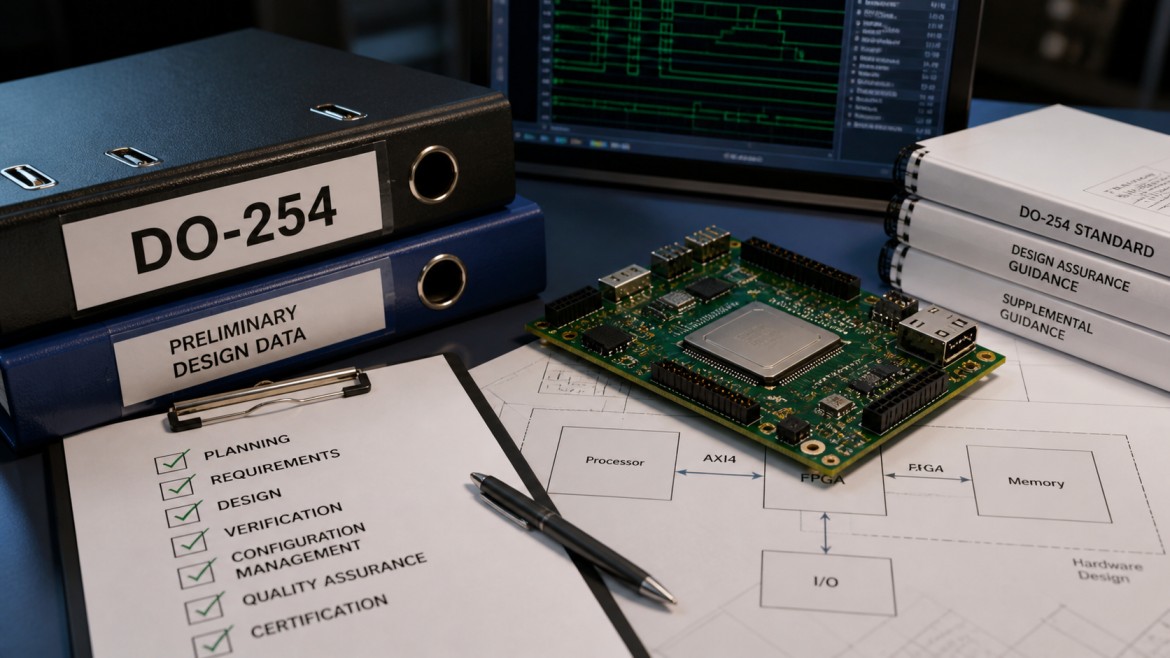

DO-254 does not prescribe how to write RTL. But working to DO-254 changes how you write RTL in practice. The standard demands complete, traceable, and verifiable hardware — and certain coding patterns make hardware impossible to fully verify. Latches, incomplete resets, and magic-number FSMs are not just code smells; in a DO-254 program they are findings that stop certification.
This post covers four concrete rules that DO-254 imposes on RTL style, with non-compliant and compliant examples for each. The final section assembles all four rules into a single verified FSM module — the building block for any safety-critical state machine design.
1. Rule 1 — No Latches: Always Provide a Default
A latch inferred by synthesis has no defined power-on state, complicates static timing analysis (it is level-sensitive rather than edge-triggered), and is impossible to reset deterministically without a dedicated asynchronous clear. In a DO-254 program, a latch inferred in a combinational block is a verified non-compliance: the hardware requirement that says “the output shall be X after reset” cannot be satisfied if the output retains whatever value it held before power was applied.
Latches arise from incomplete if-else or case statements in always_comb blocks where not every branch assigns the output. The fix is always the same: assign a default at the top of the block before the conditional logic.
[Synth 6-6904] in a DAL-A module is sufficient grounds for a reviewer to reject the design data. Run synthesis before simulation and resolve all latch and multi-driver warnings before beginning the formal verification campaign.
2. Rule 2 — Complete Reset Coverage
DO-254 requires that every register have a defined, documented post-reset state. This is not just a coding convention — it is a requirement that must be stated in the hardware requirements document and verified by a test case that asserts reset and reads back the expected values. A register that is driven inside a clocked block but absent from the reset branch has an ambiguous initial state.
Vivado flags this as warning [Synth 8-7137]: “Register X has both Set and Reset with same priority.” The synthesis tool detected that the register is driven to a known value in the non-reset branch but has no defined value in the reset branch — meaning reset and set are competing with equal precedence. This warning means the post-reset state of the register is implementation-defined, not designer-defined.
3. Rule 3 — Named States and Default Cases
An FSM written with magic number encodings (2'b00, 2'b01, …) cannot be reviewed against requirements because the mapping between state names and binary values exists only in the designer’s head. A DO-254 independent reviewer cannot verify that the reset state is correct, that the transitions match the requirements document, or that the outputs are correct in each state — without decoding the numbers manually, introducing room for error.
The second problem is the missing default case. Every case statement must include a default branch. For FSMs specifically, the default must drive next to a defined safe state — typically the reset state. This handles the scenario where radiation or a manufacturing defect corrupts the state register into an encoding not listed in the case items.
default: next = IDLE case implements this recovery — but DO-254 also requires a verification test that injects an illegal state value (by force-assigning the state register in simulation) and confirms the FSM recovers correctly. The requirement, the default case, and the test case must all trace to each other in the requirements trace matrix.
4. Rule 4 — No Simulation/Synthesis Mismatches
DO-254 requires that the verified artifact — the design data submitted to the certifier — is the same artifact that was verified. Any construct in RTL that behaves differently in simulation than in synthesis breaks this assumption and invalidates the verification evidence.
The most common sources of sim/synth mismatch are: initial blocks (simulation only — synthesis ignores them, so a register initialized in an initial block has no defined power-on state in hardware), #delay constructs (ignored by synthesis), and incomplete sensitivity lists in always @(...) blocks (simulation triggers on listed signals only; synthesis infers the correct combinational function regardless). Using always_ff, always_comb, and always_latch instead of plain always eliminates the sensitivity list problem — these keywords cause synthesis and simulation to agree by construction.
For DO-254, the rule is: RTL must be synthesizable and simulation-equivalent by construction, not by review. Use procedural blocks that enforce the contract (always_ff for registers, always_comb for combinational), and keep initial blocks out of synthesizable source files entirely.
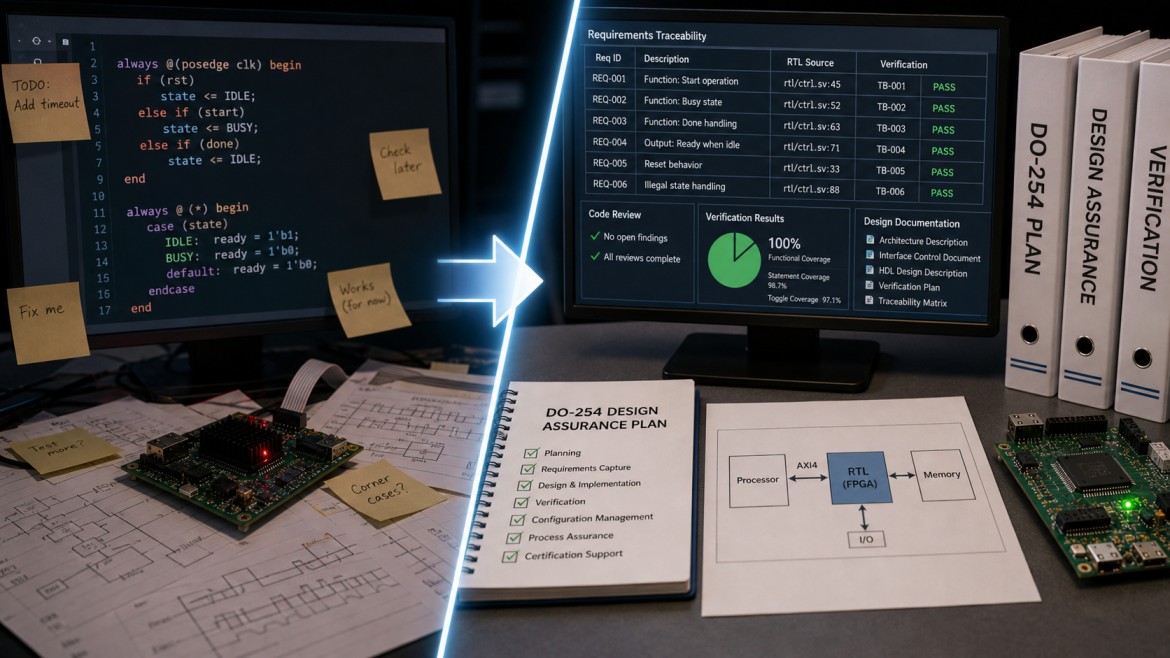
5. Putting It Together: A DO-254 Compliant Module
The safe_fsm module below applies all four rules to a four-state FSM. The typedef enum gives every state a named constant. The always_ff block has a complete reset. The two always_comb blocks — one for next-state logic, one for outputs — each start with a default assignment that prevents latch inference. The default case in both provides the stuck-in-state recovery path. The accompanying testbench covers every state transition, the output assertions in each state, and the async reset mid-operation.
safe_fsm. For a real program, structural coverage is measured by the simulation tool and reported as part of the verification evidence.
Final Thoughts: Rules Without Exceptions
The four rules in this post — no latches, complete reset, named states with defaults, no sim/synth mismatches — are not stylistic preferences. They are the minimum RTL discipline required to produce hardware that can be fully verified and independently reviewed. In a DO-254 program, each violation generates a Problem Report that must be closed before the Accomplishment Summary can be written. Closing a Problem Report late in a program — after verification evidence has already been collected — is expensive.
Apply these rules from the first line of RTL, not as a cleanup pass at the end. Running synthesis and checking for latch and reset warnings at the module level, before integration, is far cheaper than finding them during independent review. The rules exist because the certifier will check for exactly these issues — and they will find what you missed.
Happy coding.
fpgawizard.com